
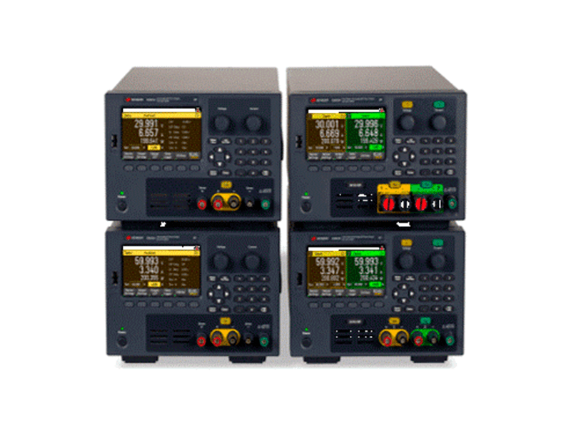
On a bench or in a system, Keysight variable DC power supplies are ready for your application, offering optimal voltage, current, capability and performance choices.
This video will help you pick the correct variable DC power supply by understanding the critical characteristics you should consider in your selection process. Key aspects of programmable DC power supplies include available power, noise requirements, programming accuracy, available software, and more.
It is a power source with an output voltage that the user can vary. Keysight variable DC power supplies allow you to change the DUT’s voltage and current.
A DC power source converts alternating current (AC) power into DC power using either a linear or switching methodology. A switching power supply has higher efficiency, reduced weight, and smaller size. Linear power supplies can achieve lower noise, but modern switching supplies have minimized or eliminated this advantage.
A programmable power supply is a power source whose output voltage, output current, output power, and other electrical output characteristics can be configured or programmed at a very fine-grained level.
However, despite their sophisticated front panel controls, knobs, displays, and powerful user interface, they’re not mere adjustable power supplies but far more than that. Their most unique aspect is that their power output behavior can be programmatically controlled in real-time using an external computer, as shown below.
A bench DC power supply is designed to sit on an engineer’s bench. It will typically have a large, legible display and a user interface so engineers can easily control all aspects of the power supply from the front panel. Users can also control modern bench power supplies via software. In addition, the output terminals are easily accessible from the front. Variable bench power supplies are handy tools for testing circuits, as they allow you to adjust the voltage on the fly.
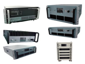
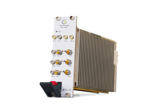
Automated test equipment (ATE) system power supplies are programmable power supplies designed for ATE systems. Size is crucial; ATE power supplies with greater power density take up less rack space and reduce the factory floor space required for test equipment.
You can combine power supplies in series to increase the total power (voltage) they can deliver. The diagram below illustrates the correct connections to achieve this.
Of course, you must set each power supply output independently so that the voltages sum to the desired value. First, set each output to the maximum desired current limit the load can safely handle. Next, set the voltage of each output to sum to the desired voltage. For example, if you use two outputs, set each to one-half the desired voltage. If using three outputs, set each to one-third of the desired voltage. In addition, when you connect outputs in series for higher voltage, you should also take the following precautions:
If you use remote sensing, please wire the remote sensing terminals on each output in series and connect them to the load.
Keep the wiring from the power supplies to the load as short as possible. Twist or bundle the leads to reduce lead inductance and noise pickup. The goal is always to minimize the loop area or physical space between the + and – output leads from the power supply to the load.
You can connect power supplies in parallel to supply additional current to a device under test. Set the current limit of all outputs equally to the sum of the desired current limit value. The diagram below shows an illustration of two DC power supplies connected correctly in parallel:
It would be best if you also obeyed the following guidelines:
Set the voltage setting of the supply operating in CV mode slightly lower than the voltage setting of the supplies operating in CC mode. The supply set higher in voltage will push current into the load until it hits CC mode. After the supply reaches CC mode, its output voltage will reduce to the level of the other connected power supply’s voltage. Those supplies will then be regulated in CV mode and contribute to the remaining load current. The paralleled supplies must end up in different operating modes, such as CV or CC. Otherwise, they will fight with each other for control, and one will win, or they will oscillate the control back and forth, which is not desirable.
Reviews
There are no reviews yet.